[Project] RPI, INA226 sensor monitoring
#
Mini project : Raspberry Pi with UPS, and INA226 Voltage I2C Module
Why ?
It has been a while since I last worked with the I2C bus and basic programs for it, but I have a good reason for revisiting it now.
My goal is to configure my Raspberry Pi as a backup for my primary Proxmox server. I intend to use it for several functions, backup website, backup file server, offering VPN access to my network if the Proxmox hypervisor fails. Additionally, I might explore creating a SDR with it in the future.
One of the advantages of using the Raspberry Pi is that it’s powered by an uninterruptible power supply (UPS) with two Li-Ion batteries. I want to monitor these batteries to ensure I can gracefully shut down the Pi if needed and to estimate how long it can run on battery power.
Components
Core project :
- A Raspberry Pi, here the 4B 2Gb, but it doesnt really matter
- INA226 current/voltage module
- Cheap aliexpress UPS module
Optionally :
- A 12v fan
- Breadboard
- Module to power the breadboard
- NVME to USB adapter
- NVME Drive (overkill for rpi4)
- Heatsink for the cpu
Building something to hold everything
I had a piece of acrylic and some nice wood, which I assembled to create two base linked together. This setup allows me to securely mount everything using M2 stands and screws. On it, I placed the NVMe SSD, the UPS module, and provided space for a small breadboard to facilitate wiring and to accommodate the INA226 module.
The result is this :
#picture
Proof of cocnept on arduino
I usually prefer to test my modules on an Arduino, and occasionally on an STM32 if I have extra time. This allows me to see how the libraries handle everything and ensures the I2C bus interfacing works correctly.
By doing this, I minimize the risk of damaging a Raspberry Pi or a computer, as I’m only putting an Arduino clone or the module itself at risk if something goes wrong.
This time, I decided to try out a USB-C Arduino Mini knockoff from AliExpress. I found it good visually for quick interfacing with various projects.
#picture
Interfacing the Module on the RPI
The goal is to collect power consumption data for the entire circuit, so we only need to measure the current since the bus operates at a fixed 5V. The voltage sensor will be used to monitor the Li-ion batteries of my UPS.
Here’s the setup:
- Current: Measures the current on the 5V bus
- Power (calculated): current * 5V
- Shunt: Voltage drop used to measure current
Voltage: Measures the voltage of the UPS batteries
- Power (module): Not used
Since the module’s power register assumes that both the current and voltage come from the same source, using it would result in incorrect power calculations
UPS Issues
The UPS is a cheap board from aliexpress, cheap mean that it sometimes comes with little problems to resolve, to make it fast here it goes :
- Voltage drop is quite high
- Noise on the 5V bus
I first noticed something was wrong when my Raspberry Pi started logging low voltage warnings in the kernel journal. After investigating, I discovered the CPU frequency was dropping significantly. You can check this with the following command:
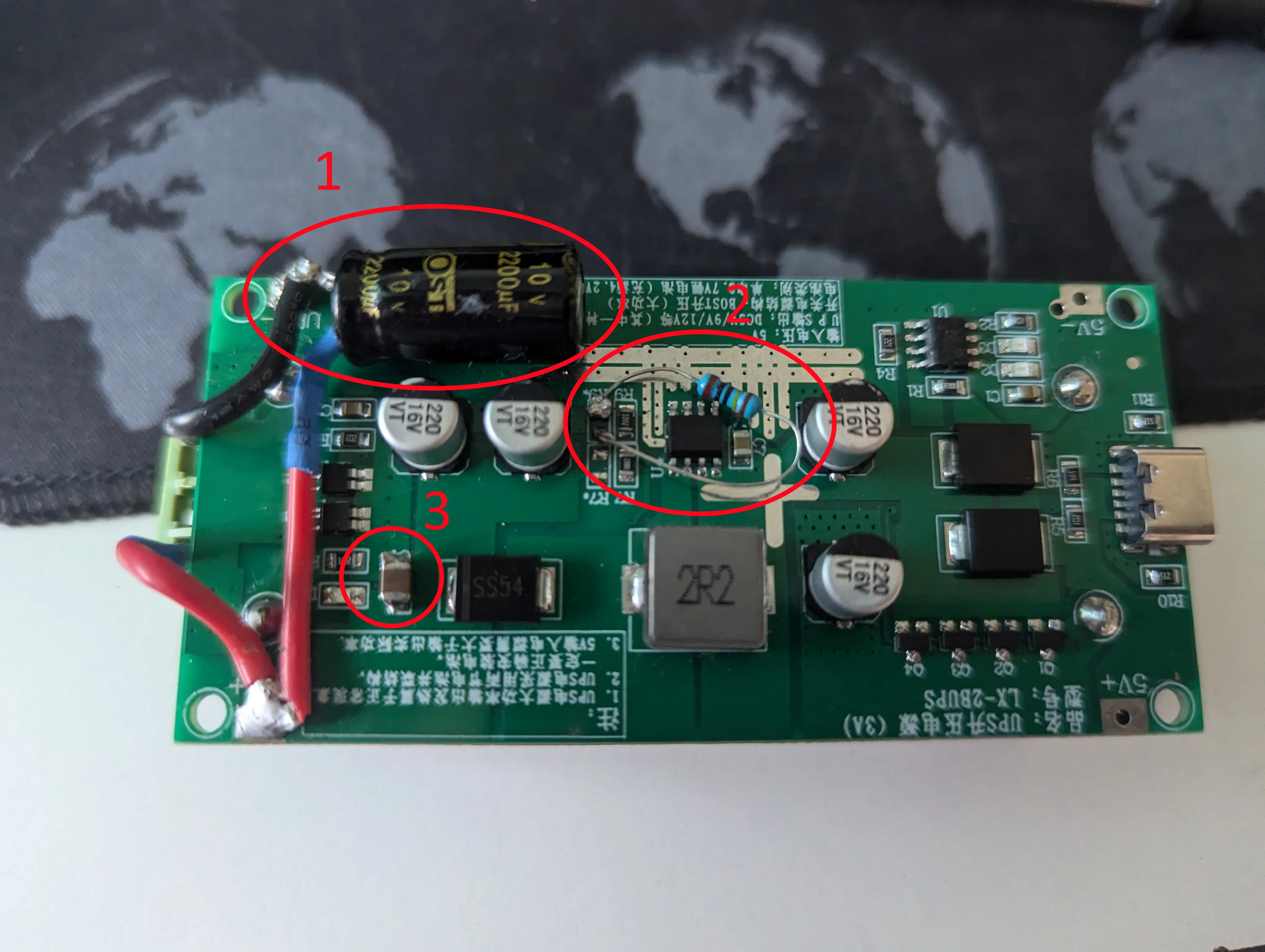
To solve this, I started thinking that some voltage drop occur when there is current spike, and adding a 2200uF capacitor should be resolving this, however it doesnt worked so far
After more research, I found a video by GreatScott! that covered the same issue. In the video, he analyzes the output bus with an oscilloscope and identifies significant noise on the bus: https://youtu.be/NjNOGm3sCOQ?
In this second video, he show how to fix it : https://youtu.be/6bicunweBAQ?feature=shared&t=351
He then proceed to change one of the bus capacitor with a smaller but more reliable one, I found one of good quality on a Old DVD reader that used good quality component used at high frequency, perfect for this case !
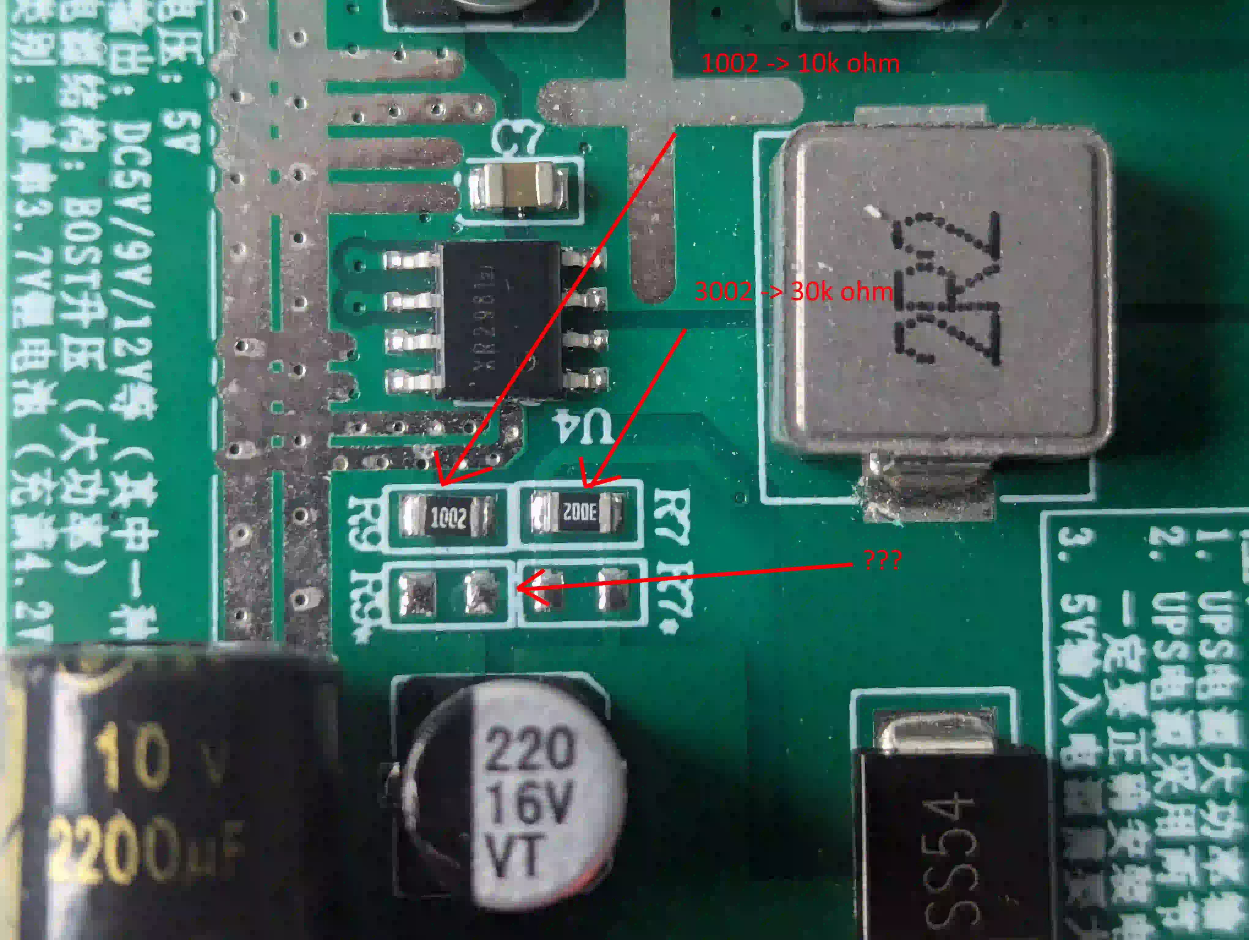
Despite these efforts, the low voltage warning persists. Next step is to increase the bus voltage from around 4.9V to over 5.05-5.1V. To achieve this, I need to adjust the voltage divider for the XR2981 chip
To do this I need to change the value of the voltage divider for the XR2981 chip,
Since I didn’t have the right SMD resistors, I improvised with a basic resistor, as you can see in the second picture. It doesn’t look great, but it works
You can find the exact calculation in the datasheet, page “7”, “OUTPUT VOLTAGE PROGRAMMING”
link : https://cdn.hackaday.io/files/1829407826904960/Xysemi_XR2981.pdf backup:
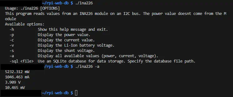
C Program
I found a codebase that provides a solid foundation for what I want to achieve, with all the necessary registers already defined and written in C. I only need to implement the specific features I require.
For now, I’ve added argument passing to collect data in a more conventional manner. You can find my modified code, along with the forked repository, in the Readme.
The program is currently running quite fast, making it a good to be used as a Linux daemon. I’ll explore that further once the SQLite integration is complete.
https://github.com/alxblzd/rpi-web-db-ina226